With this App you can control a HP Powerbox (HP8440 and HP8441) from your iPhone on the go. For this to work your powerbox just needs to have a bluetooth chip inside, But don’t worry, this can be done quite easily. And here is how.
First things first
I am not involved with the development of the Powerbox itself. I don’t work for or speak for the company that builds it, sells it, imports it or supports it. This is just a Fan based project because I and a lot of colleagues like the product and use it almost every day and this App has been helpful for years. Modifying or opening the box will probably void your warranty. I take no responsibility for the mod.
What you need
Well first of all you need a HP8440 or HP8441 Powerbox you want to control and a „HM-10“ bluetooth chip as well a 2 resistors and a small electrical switch. I use these Bluetooth HM10 Chips from DSD and they work quite well while some others have problems with the AT commands.
- Prepare HM10: First of all you have to change the baudrate of the HM10 to 38400 baud. And, if you want you can change the Bluetooth name to something like „Powerbox“. This can be done by connecting the HM10 to your PC and sending the AT Commands „AT+NAMEPowerbox“ and „AT+BAUD4“ (in most cases 4 is 38400). NO other commands are needed. If you dont care about the name, the AT+BAUD command is the only one needed at all to change the baudrate to 38400 and nothing else. How this is done can be found just by googling „HM-10 AT Commands“ all over the internet, such as here.
2. Install HM10: Once the HM10 has been prepared you just have to build this easy circuit and connect it to the powerbox‘ pcb. Basically we just want the internal UART to the microcontroller in the powerbox to be accessible via Bluetooth:
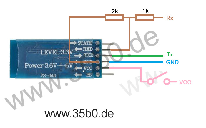
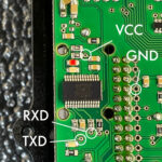
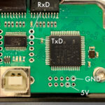
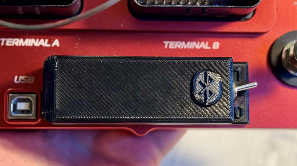
The Switch is neccessary because once the bluetooth chip is turned on, the USB Port on the Powerbox is not usable anymore. In order to use the USB Port again you just switch the BT chip off and you can configure the Powerbox via a USB again. Here are the connection points on the pcbs:
After this you can mount the Bluetooth chip anywhere you like. Just keep in mind that the metal housing of the Powerbox will shield the radio signals. I have 3D printed an external thing that sits on top of the box and also houses the resistors and the switch:
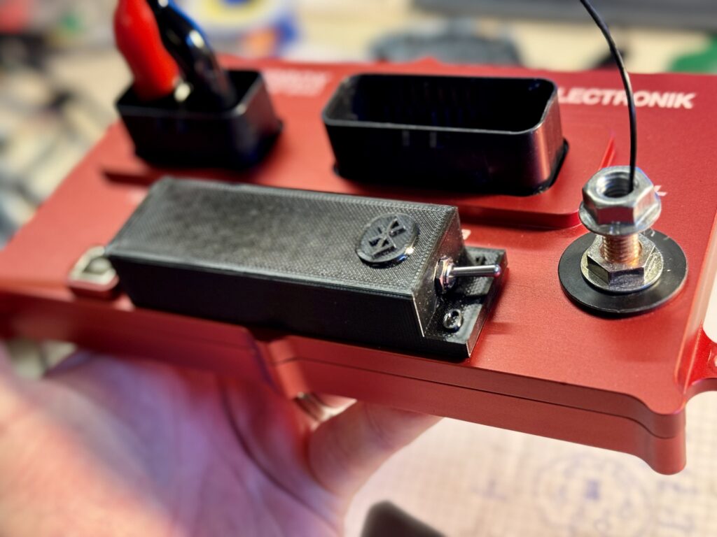
Note: Make sure to glue the soldered points or they might damage the pcb when the wire pull on them.
Note2: If it doesn’t work at first, maybe you have reversed Rx and Tx, common mistake 😉
The App
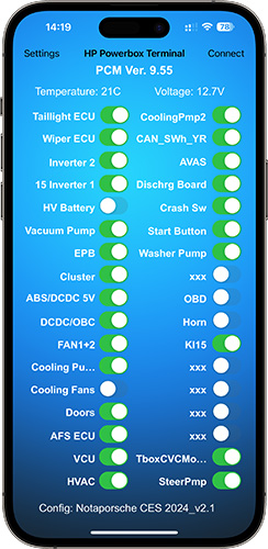
After you are done modifying the box you can start the app, click on „Connect“ and a list of available Powerboxes nearby will be shown. Click on one to connect to it. Here is a video of me showing this for anyone interested.
Now all the switches in the app will switch themself to the current status of the output that the Powerbox has now. You can now use the switches to turn on and off every output individually from your smartphone. Also other things like Voltage, Temperature etc. can be monitored in the app in almost realtime.
The configuration
The App supports configuration strings. With this you can for example rename the outputs in the App for more convenient use.
The string can be written in any text editor app and can contain the following data:
VER(Your description)VER#
With this you can give your config a name
CH1(Channel description)CH1#
This changes the name to every channel. Channels 1-34 are supported.
So with this you could create a configuration like this:
VERVehicle1234_v2.1VER#CH1Taillight ECUCH1# CH2Wiper ECUCH2# CH3Inverter 2CH3# CH415 Inverter 1CH4# CH5HV BatteryCH5# CH6Vacuum PumpCH6# CH7EPBCH7# CH8ClusterCH8# CH9ABS/DCDC 5VCH9# CH10DCDC/OBCCH10# CH11FAN1+2CH11# CH12Cooling Pump1CH12# CH13Cooling FansCH13# CH14DoorsCH14# CH15AFS ECUCH15# CH16VCUCH16# CH17HVACCH17# CH18CoolingPmp2CH18# CH19CAN_SWh_YRCH19# CH20AVASCH20# CH21Dischrg BoardCH21# CH22Crash SwCH22# CH23Start ButtonCH23# CH24Washer PumpCH24# CH25xxxCH25# CH26OBDCH26# CH27HornCH27# CH28Kl15CH28# CH29xxxCH29# CH30xxxCH30# CH31xxxCH31# CH32xxxCH32# CH33TboxCVCModemCH33# CH34SteerPmpCH34#
A default configuration would look like this:
VERDefault ConfigurationVER#CH1Output 1CH1# CH2Output 2CH2# CH3Output 3CH3# CH4Output 4CH4# CH5Output 5CH5# CH6Output 6CH6# CH7Output 7CH7# CH8Output 8CH8# CH9Output 9CH9# CH10Output 10CH10# CH11Output 11CH11# CH12Output 12CH12# CH13Output 13CH13# CH14Output 14CH14# CH15Output 15CH15# CH16Output 16CH16# CH17Output 17CH17# CH18Output 18CH18# CH19Output 19CH19# CH20Output 20CH20# CH21Output 21CH21# CH22Output 22CH22# CH23Output 23CH23# CH24Output 24CH24# CH25Output 25CH25# CH26Output 26CH26# CH27Output 27CH27# CH28Output 28CH28# CH29Output 29CH29# CH30Output 30CH30# CH31Output 31CH31# CH32Output 32CH32# CH33Output 33CH33# CH34Output 34CH34#
I think this does not need any other explanation. The sequence of the commands in the config line don’t matter by the way.
Notes
The app will be expanded in the future as new ideas and features keep coming in. The app has been tested and confirmed working with firmware 9.42 and 9.55 but should work with all versions. 9.55 is the newest at the time of this writing, so why not just use the newest one 🙂
The App is available on the Apple Appstore: